Content Menu
● Eddy Current Separation: Core Concepts and Principles
>> How an Eddy Current Separator Works
>> Operation of an Eddy Current Separator in Practice
● Key Separation Variables for Eddy Current Separators
>> The Influence of Particle Shape
>> Eddy Current Separator Variables: Rotor Speed
>> Rotor Configuration: Concentric vs Eccentric
>> Rotor Magnetic Strength and Field Depth
>> Selecting the Right Rotor for the Application
● Applications and ECS Model Types
>> Typical Eddy Current Separator Applications
>> Eddy Current Separator Model Families
● Electrostatic Separation: Principles and Capabilities
>> How Electrostatic Separation Works
>> Charging Mechanisms and Corona Charging
>> Operation of a Roll‑Type Electrostatic Separator
● Electrostatic Separation Variables and Process Conditions
>> Material Variables for Electrostatic Separation
>> Electrostatic Separator Settings
>> Environmental and Electrode Control
● Electrostatic Separation Applications and Throughputs
>> Typical Electrostatic Separation Applications
● Eddy Current vs Electrostatic Separation: Side‑by‑Side Comparison
● Designing Process Lines: When to Use ECS, Electrostatic, or Both
>> Typical Hybrid Flowsheet in Recycling
>> Practical Optimisation Tips for Plant Engineers
● Strategic Benefits of Combining Eddy Current and Electrostatic Separation
● Summary
● Frequently Asked Questions (FAQ)
>> Q1. When should I choose an eddy current separator instead of an electrostatic separator?
>> Q2. In which situations does electrostatic separation offer a clear advantage?
>> Q3. Can I run eddy current and electrostatic separators in the same process line?
>> Q4. How important is particle size control for these technologies?
>> Q5. How can I estimate the payback period for installing ECS or electrostatic equipment?
Metal recyclers, WEEE processors, and mineral processing plants increasingly rely on advanced separation technologies to maximise metal recovery and product purity from complex waste streams.
In modern plants, eddy current separators and electrostatic separators are two of the most important tools for recovering valuable non‑ferrous metals that would otherwise be lost to landfill or low‑value residues.
Understanding how each technology works, where it performs best, and how they can be combined in a single flowsheet is essential for achieving higher recovery, stable operation and better financial returns.
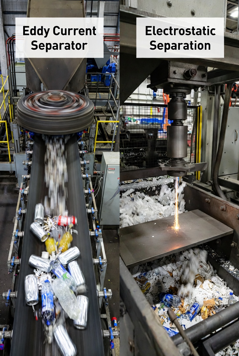
Eddy Current Separation: Core Concepts and Principles
The eddy current separator (ECS) is widely used in the recycling industry to recover or remove non‑ferrous metals such as aluminium, copper and zinc from non‑metallic materials.
Different rotor and machine designs allow the separation of both small non‑ferrous particles, down to around 3 mm, and larger pieces such as beverage cans and mixed scrap metals.
In most recycling lines, the ECS is installed after primary ferrous separation and is often part of a larger metal separation module that also includes overband magnets or drum magnets.
How an Eddy Current Separator Works
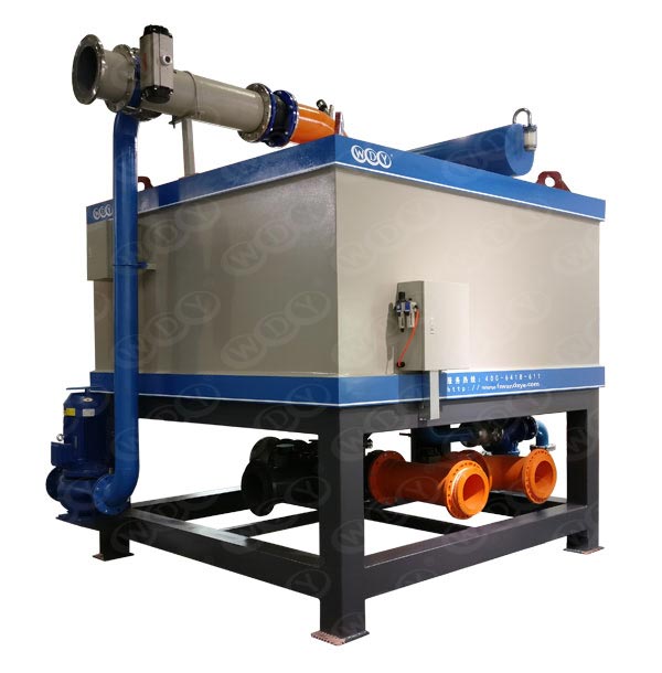
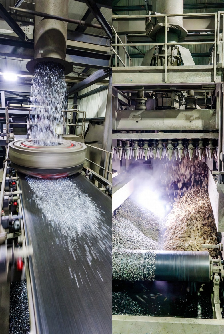
An eddy current separator is typically a dual‑pulley conveyor system where the non‑metallic head pulley houses an independently rotating high‑speed magnetic rotor.
When non‑ferrous metal particles are conveyed into the magnetic zone, they are exposed to a rapidly changing magnetic polarity created by the multiple poles of the rotor.
According to Faraday’s Law of induction, electric currents are induced when a conductive particle enters this rotating magnetic field, and by Lenz’s Law these induced eddy currents generate a magnetic field that opposes the original field and creates a repulsive force on the metal particle.
The two magnetic fields oppose each other, resulting in a strong repulsion that changes the trajectory of the non‑ferrous particle, while non‑conductive host material follows a normal ballistic path off the head pulley.
A carefully positioned splitter blade intercepts these different trajectories, allowing the non‑ferrous metals to be thrown over the splitter into a separate collection zone, while non‑metallic material falls short into another chute.
Operation of an Eddy Current Separator in Practice
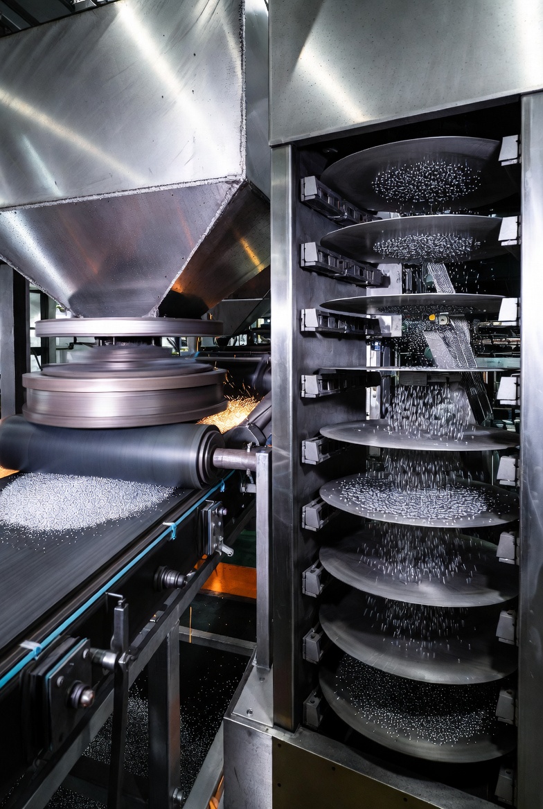
In operation, a mix of non‑magnetic material within a defined particle size range is fed via a conveyor or controlled feeder onto the ECS belt.
The ECS belt usually runs faster than the upstream feed conveyor so that material spreads out, ideally forming a stable mono‑layer rather than a thick burden that shields smaller particles.
As the material travels towards the head pulley, non‑ferrous metals entering the separation zone experience repulsive forces that project them forward, while the host material drops down under gravity.
The rejected non‑ferrous metals are propelled over the splitter and onto a collection conveyor or into bins, whereas the non‑metallic residue falls behind the splitter into a separate discharge point.
Correctly setting the belt speed, splitter angle and feed presentation is critical to achieving a clean separation and high recovery of non‑ferrous metals.
Key Separation Variables for Eddy Current Separators
The performance of an ECS depends on both material characteristics and machine settings, and optimising these variables can significantly improve recovery and product quality.
Engineers should pay particular attention to the conductivity and density of the metals, particle size and shape, feed preparation and rotor design when specifying and commissioning an ECS.
Material‑Side Variables
For a separation to occur, the eddy current forces produced by the rotor must induce enough energy to create a strong reaction in the metal particle.
The amount of energy induced into a particle is proportional to its electrical conductivity, size, shape and weight or density, as well as the behaviour of the surrounding non‑metallic material.
Metals with a high conductivity‑to‑density ratio, such as aluminium, generally react strongly and are easier to separate than denser, lower conductivity metals.
In practice, powerful ECS designs can impart enough energy into particles with a high conductivity‑density ratio to produce a reaction on particles as small as about 3 mm, provided the host material is tightly sized.
However, as the particle size distribution of the host material becomes broader, the ability to separate such small non‑ferrous metals diminishes because the lighter fine particles do not travel far enough to cross the splitter.
The Influence of Particle Shape
Particle shape is another critical separation variable that determines how effectively the ECS can act on each piece of metal.
Flat particles tend to respond very well to eddy current forces; they flip and lift as the induced currents act across a larger surface area in the magnetic field.
By contrast, spheres and wires are more difficult to separate because the eddy current force often causes them to simply turn or spin without producing a strong directional repulsion away from the rotor.
This means that even when conductivity and size are favourable, the geometry of the metal pieces can limit separation efficiency.
Engineers should therefore consider upstream shredding or granulation settings that promote particle shapes more favourable for ECS separation where possible.
Eddy Current Separator Variables: Rotor Speed
To inject the maximum amount of repulsive energy into a non‑ferrous metal particle, there must be sufficient dwell time as the particle passes through the alternating magnetic field.
If the rotor speed is too high, the period of interaction between the particle and the changing field becomes too short, and inadequate energy is transferred to achieve a clean separation.
In practice, the optimum rotational speed is specific to each rotor design and application, but is commonly found in the range of roughly 2000 to 5000 rpm, with many systems operating between 2000 and 3000 rpm to balance performance and mechanical wear.
Higher speeds increase mechanical stress and bearing wear, so long‑term reliability must be considered alongside separation efficiency when selecting operating speeds.
Regular monitoring of vibration, temperature and rotor condition helps ensure that ECS units running at high speeds remain stable and safe over time.
Belt Speed and Feed Method
Because different ECS designs use varying rotor diameters, pole counts and magnetic strengths, there is no universal belt speed that suits all materials and applications.
The optimum belt speed depends on the rotor characteristics and on the size, density and flow behaviour of the non‑ferrous particles to be separated.
In general, the belt must be long enough or the feed system well controlled so that the material is settled and well distributed before entering the separation zone.
The highest levels of separation are often achieved when material is fed onto the ECS via a vibratory feeder that delivers a consistent, controlled flow and forms a mono‑layer before dropping onto the belt.
If material is fed directly from another conveyor, a longer ECS belt is usually needed to give the material time to settle; if fed from a good vibratory feeder, a shorter belt and more compact layout are possible.
Rotor Configuration: Concentric vs Eccentric
The eddy current separator is a conveyor with a magnetic rotor acting as the head pulley, and this rotor can be configured in either concentric or eccentric designs.
On machines with concentric rotors, the magnetic rotor spins uniformly within the non‑magnetic shell, creating a symmetric field around the circumference.
However, because the rotor attracts ferrous material as well, it can be difficult to discharge magnetic contaminants from the belt on concentric designs, and any trapped ferrous pieces can heat up and damage the belt or shell when the conveyor stops.
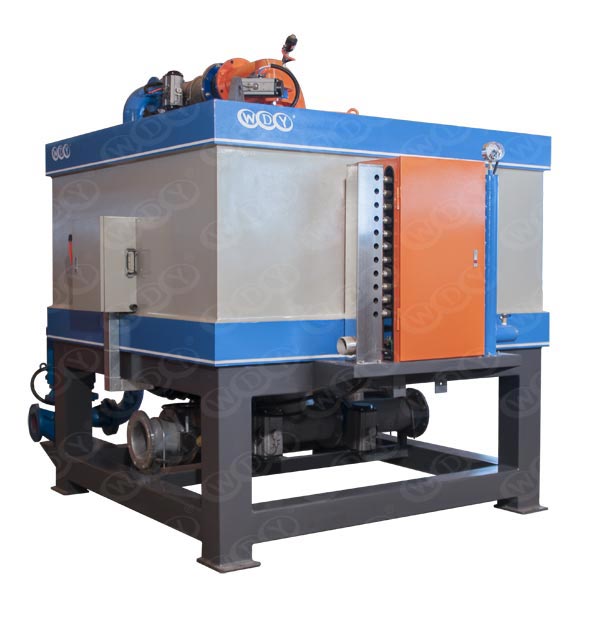
Eccentric rotors place the rotor closer to one quadrant of the shell, concentrating the field in the separation area and allowing ferrous particles to be pulled out of the field by the conveyor and discharged beneath the rotor into the non‑metallic fraction.
Regardless of rotor configuration, it remains good practice to remove ferrous metals upstream using appropriate magnetic separators to protect the rotor and maximise non‑ferrous recovery.
Rotor Magnetic Strength and Field Depth
A common assumption is that stronger magnetic rotors always produce better levels of separation, but in practice the design and geometry of the magnets, as well as the distance to the belt surface, are just as important.
All ECS rotors are built from permanent magnets fixed to a carrier pulley, and the length and thickness of these magnets determine the depth of the magnetic field, often referred to as the field “throw”.
Longer and thicker magnets generate deeper magnetic fields, which are advantageous for larger particles requiring a field projected into their centre, while shorter magnets create shallower but more intense fields close to the surface.
In all cases, maximum magnetic intensity occurs at the magnet surface, and some intensity is naturally lost as the field passes through the air gap, non‑metallic shell and conveyor belt before reaching the material layer.
This means that a rotor built with very short, extremely strong rare earth magnets can sometimes produce a weaker effective field at the belt surface than a rotor using longer, somewhat lower‑strength ferrite magnets, depending on the design and measurement point.
Selecting the Right Rotor for the Application
Because field depth and field intensity at the belt surface both matter, it is difficult to classify any rotor as simply “strong” or “weak” without stating where and how the measurement is taken.
For large non‑ferrous particles, such as aluminium cans, a deeper magnetic field is preferred so that the field penetrates into the centre of the particle and generates strong repulsive forces.
For small non‑ferrous particles, such as granulated cable, a shallower field with short, powerful magnets often performs better because the separation occurs very close to the belt surface where the fine metal pieces reside.
Rotor selection should therefore be based on the size range and type of non‑ferrous metals to be separated, as well as the machine’s role within the overall process line.
Where possible, test work using representative material should be undertaken to confirm the best rotor design for the specific separation objectives.
Applications and ECS Model Types
Eddy current separators are successfully used in a wide range of recycling and processing applications to recover or remove non‑ferrous metals from complex streams.
The separation performance and throughput depend on the material characteristics, such as size distribution, metal content and contamination levels, and are usually validated through controlled tests at specialist test centres.
Typical Eddy Current Separator Applications
Common ECS applications include recovering and cleaning non‑ferrous metals from:
– Auto shredder residue, where aluminium and other non‑ferrous metals are recovered from mixed car scrap
– Municipal solid waste, for the recovery of aluminium beverage cans and mixed non‑ferrous metals
– Glass cullet, where aluminium caps and other non‑ferrous contaminants must be removed to protect furnaces and ensure glass quality
– Plastics recycling, where metals are removed from regrind to protect extrusion and injection moulding equipment
– Wood, biomass and refuse‑derived fuels, where metal removal lowers maintenance and improves boiler reliability
Eddy Current Separator Model Families
To maximise non‑ferrous separation across different feeds, suppliers typically offer several ECS models tailored to specific size ranges and applications.
Examples of model types include:
– High‑Intensity Concentric ECS for small non‑ferrous metals from around 50 mm down to 5 mm
– High‑Intensity Eccentric ECS for fine non‑ferrous metals below about 10 mm
– General‑purpose ECS designs for recycling applications where non‑ferrous metals are mostly above 20 mm
– Dedicated can sorter ECS units engineered specifically for high‑throughput separation of aluminium beverage cans
Selecting the appropriate ECS model is essential to ensure that both the particle size range and throughput match the plant’s objectives and available footprint.
Electrostatic Separation: Principles and Capabilities
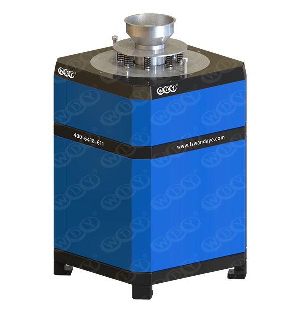
Electrostatic separation is a complementary technology to eddy current separation and is particularly valuable for the recovery of fine conductive particles that ECS units struggle to treat effectively.
An electrostatic separator typically processes materials in the size range from about +45 microns to 4 mm, enabling recovery of metals that might otherwise be lost to dust or mixed fines.
How Electrostatic Separation Works
Every material exhibits electrostatic behaviour when exposed to an external electrostatic field, and this property can be used for separation based on conductivity differences.
In metal recycling, materials are broadly categorised as conductors, mainly metals, and non‑conductors or dielectrics, such as plastics, glass and stone.
When a high‑voltage electrostatic field is applied, conductive particles quickly lose their charge to an earthed surface, while non‑conductive particles retain the charge and become pinned to the earthed roll by an image force.
This phenomenon allows the separation of highly conductive metals from lower conductivity metals, such as aluminium from copper, or the separation of metals from plastics in granulated cable streams.
Electrostatic separation thus exploits differences in electrical conductivity to produce clean metal and non‑metal fractions, often in particle sizes that would otherwise be very difficult to handle in dry processes.
Charging Mechanisms and Corona Charging
There are three main methods by which particles can be charged in electrostatic systems: charging by ion bombardment, charging by induction and tribo‑charging through friction.
For high‑throughput metal recycling and mineral processing applications, charging by ion bombardment, often referred to as corona charging, is generally the most efficient and controllable approach.
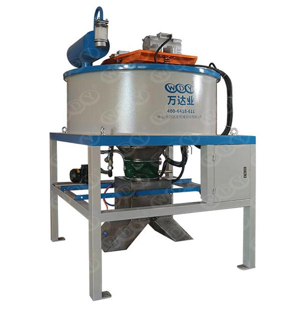
In a typical roll‑type electrostatic separator, a high‑voltage electrode is used to create a corona discharge that ionises the air and charges incoming particles as they approach the roll.
This controlled charging mechanism ensures consistent particle behaviour in the separation zone and supports continuous operation at several tonnes per hour for free‑flowing materials.
By adjusting voltage, electrode position and other parameters, operators can fine‑tune the separation to meet specific recovery and purity targets.
Operation of a Roll‑Type Electrostatic Separator
Feed material, such as granulated copper cable, is delivered by a controllable vibratory feeder onto a revolving earthed roll in a thin, consistent mono‑layer.
A voltage, typically in the range of 20 to 30 kV, is applied to the static electrode, generating a strong electrostatic field as the particles fall onto the roll surface.
Conductive particles, for example copper or aluminium, instantly lose their charge to the earthed roll and are thrown off by the centrifugal force created by the rotation of the roll.
Insulating particles, such as plastic insulation, retain their charge and create an image force that pins them to the roll until they are removed by a brush or scraper into a separate discharge chute.
This continuous process allows the separator to generate distinct streams of conductors, non‑conductors and sometimes a middlings fraction, which can be recirculated for further processing and improved liberation.
Electrostatic Separation Variables and Process Conditions
As with ECS technology, the performance of electrostatic separation depends heavily on both material properties and machine settings.
Optimising factors such as particle size range, moisture content, applied voltage, roll speed and ambient humidity is essential for stable and efficient operation.
Material Variables for Electrostatic Separation
Electrostatic separators perform best with material in the size range from about plus 45 microns to minus 4 mm, allowing plants to treat fine fractions that are difficult to process with eddy current separators.
Closer particle size distribution significantly increases separation efficiency because roll speed, electrode position and splitter settings can be tuned more precisely for a narrower size band.
Excess fine material below 45 microns should be controlled or treated separately, as large amounts of ultra‑fines can inhibit separation efficiency, cause feeding problems and reduce effective capacity.
Surface moisture strongly inhibits electrostatic separation because a thin water film alters conductivity and charge behaviour, so feed must be relatively dry and free‑flowing.
Pre‑drying, thermal conditioning or operating in a controlled humidity environment may be necessary for some materials to ensure consistent, high‑quality separation results.
Electrostatic Separator Settings
The key control variables for electrostatic separators include applied voltage, roll speed, splitter plate position, humidity control and electrode position.
The applied voltage is usually set between 20 and 30 kV, and adjusting this value changes the strength of the image force that pins insulators to the roll, thereby influencing the grade and recovery of each fraction.
Higher applied voltages increase the image force and cause more material to be pinned, which can be useful when separating partially liberated metal‑plastic composites.
Roll speed determines the centrifugal force acting on conductive particles, and balancing roll speed with voltage is essential to create a clear separation between conductors and non‑conductors.
Adjustable splitter plates define the cut points between fractions, and in some applications a third splitter creates a middlings stream that can be returned to earlier stages such as shredding or granulation for improved liberation.
Environmental and Electrode Control
Low humidity atmospheric conditions generally favour electrostatic separation, as high humidity and condensation can interfere with particle charging and image force effects.
Many commercial electrostatic separators therefore include optional heating or enclosure systems to control relative humidity and maintain stable performance even in challenging climates.
Electrode position is another crucial tuning parameter; by moving the tungsten electrode closer or further from the roll and adjusting its angle, operators can optimise sensitive separations between materials with similar conductivity.
Careful commissioning tests are usually carried out to determine the best combinations of voltage, electrode geometry, roll speed and splitter positions for each specific material stream.
Once optimised, these settings are documented and used as reference recipes for consistent day‑to‑day operation and rapid recovery after maintenance or product changeovers.
Electrostatic Separation Applications and Throughputs
Electrostatic separation has a long history in the mineral processing industry and is now widely adopted in metal recycling and specialty applications where fine metal recovery is essential.
Typical throughputs for metal recycling applications are in the range of two to three tonnes per hour per metre of machine width, though actual capacity always depends on material properties and process objectives.
Typical Electrostatic Separation Applications
Common electrostatic separation applications include:
– Secondary metal recycling, including recovery of precious and base metals from complex residues
– Granulated copper cable processing, separating copper from plastic insulation even at fine sizes
– Separation of aluminium from plastic in shredded window frames and laminated structures
– Separation of copper from mixed copper‑aluminium products to upgrade product quality
– Mineral sands processing, often in combination with high‑intensity magnetic separators for ilmenite, rutile and other minerals
– Shredded WEEE and auto shredder residue fines, where fine metal recovery is otherwise difficult
– Specialised food and industrial separations where conductivity differences can be exploited
Because of its ability to handle fine particle sizes and very small metal pieces, electrostatic separation often delivers incremental revenue from material streams that might previously have been treated as waste.
Eddy Current vs Electrostatic Separation: Side‑by‑Side Comparison
For plant designers and engineers, it is useful to compare the key differences between ECS and electrostatic technologies to define their role in the flowsheet.
In many cases the most profitable solution is not choosing one or the other, but combining both in a staged process to cover the full particle size range.
| Aspect | Eddy Current Separator | Electrostatic Separator |
|---|---|---|
| Primary separation basis | Electromagnetic induction and repulsive forces acting on conductive metals in a changing magnetic field | Differences in electrical conductivity in a static high‑voltage electrostatic field |
| Typical size range | Generally 3 mm and above, best performance above about 5 mm | Plus 45 microns up to about 4 mm |
| Main target materials | Non‑ferrous metals (aluminium, copper, zinc, etc.) versus non‑conductors | Conductors versus non‑conductors, or different metals with distinct conductivities |
| Feed condition | Dry, free‑flowing material with ferrous metals mostly removed | Dry, low surface moisture, narrow size distribution and controlled fines |
| Typical process location | After ferrous separation and coarse screening, often first stage non‑ferrous recovery | After size reduction and classification, commonly treating fine or mixed fractions and ECS residues |
| Key control variables | Rotor speed, belt speed, feed presentation, splitter position, rotor design and magnetic field depth | Applied voltage, roll speed, electrode position, splitter settings, feed rate and humidity control |
| Best‑fit examples | Cans, coarse non‑ferrous recovery from ASR, MSW, glass cullet and plastics lines | Fine copper cable, aluminium‑plastic composites, mineral sands and fine WEEE or dust fractions |
Designing Process Lines: When to Use ECS, Electrostatic, or Both
From a process engineering perspective, eddy current and electrostatic separation should be viewed as complementary stages within a broader, integrated separation strategy.
The most successful plants use magnetic separators, ECS units and electrostatic systems in sequence, with screening and size reduction between stages to present each technology with the ideal feed conditions.
Typical Hybrid Flowsheet in Recycling
A common high‑performance hybrid layout for WEEE, ASR or complex waste streams may follow a series of steps such as:
1. Primary ferrous separation using overband magnets or drum magnets to remove steel and strongly magnetic items
2. Sizing and classification to split the material into coarse and fine fractions that are easier to treat separately
3. Eddy current separation of the coarse fraction to recover larger non‑ferrous metals at high throughput
4. Further size reduction and screening of ECS residue to liberate embedded metals and create narrow fine size bands
5. Electrostatic separation of the fine and mixed fractions to recover additional conductive metals and split similar metals where required
6. Middlings re‑processing, where partially liberated material is returned to granulation or shredding for improved liberation and subsequent re‑treatment
By treating coarse and fine fractions with the most appropriate technology, plants can maximise overall metal yield while maintaining stable operating conditions and manageable maintenance workloads.
Practical Optimisation Tips for Plant Engineers
To extract maximum value from existing equipment, engineers can implement a number of practical optimisation actions across both ECS and electrostatic stages.
For eddy current separators, it is important to tighten particle size bands feeding each machine, especially when targeting metals below 10 mm, as this improves both recovery and purity.
Fine‑tuning rotor and belt speeds through controlled trials helps find the best compromise between dwell time and stable material trajectories for the specific material mix.
Improving feed presentation with well‑designed chutes and vibratory feeders can transform inconsistent burden depths into uniform mono‑layers that separate much more cleanly.
For electrostatic separators, maintaining low moisture in the feed and controlling ambient humidity are central to consistent operation, and simple drying or heating steps can often unlock major performance gains.
Systematic trialling of voltage, roll speed, electrode position and splitter settings using plant material, supported by laboratory or pilot‑scale testing if available, helps define robust operating “recipes” for each material stream.
Strategic Benefits of Combining Eddy Current and Electrostatic Separation
When used together with appropriate magnetic separation, ECS and electrostatic separators enable very high levels of metal recovery from complex waste streams that were once considered uneconomical to process.
In practice, eddy current separators are ideally suited for recovering and cleaning non‑ferrous metals above roughly 3 mm, where their capacity and robustness provide a strong first recovery stage.
Electrostatic separators complement this by handling the smaller fraction, efficiently separating and recovering conductive metals from around 4 mm down to plus 45 microns where ECS performance becomes limited.
Electrostatic technology also has the ability to separate different conductive metals, such as copper from aluminium, on tightly sized fractions, creating high‑purity metal products with premium market value.
By integrating these technologies properly, operators can significantly increase the proportion of waste material that is reclaimed, reused and recycled, while improving the revenue generated per tonne of input feed.
Summary
Eddy current and electrostatic separation technologies are now central to high‑efficiency metal recovery in recycling and mineral processing plants handling complex, mixed and fine material streams.
ECS units provide robust, high‑capacity separation of coarse non‑ferrous metals, while electrostatic separators unlock value from fine fractions and enable selective separation between different metals and metal‑plastic composites.
Optimal results are achieved when both technologies are integrated into a carefully engineered process line that also includes appropriate magnetic separators, size reduction and screening stages.
By investing in proper testing, equipment selection and ongoing optimisation, operators can maximise metal yield, improve product purity and strengthen the economic performance of their recycling or processing operations.
Contact us to get more information!
Frequently Asked Questions (FAQ)
Q1. When should I choose an eddy current separator instead of an electrostatic separator?
An eddy current separator is the preferred choice when your main goal is to remove or recover non‑ferrous metals larger than about 3 mm from a mixed non‑metallic stream such as auto shredder residue, municipal solid waste or glass cullet.
ECS units are mechanically robust, relatively simple to operate, and deliver high throughput, making them ideal as the first non‑ferrous recovery stage after ferrous separation.
Q2. In which situations does electrostatic separation offer a clear advantage?
Electrostatic separation offers a clear advantage when you are dealing with fine particles below roughly 4 mm or when you need to separate metals from plastics or different metals from one another based on subtle conductivity differences.
It is especially valuable for granulated cable, aluminium‑plastic composites, fine WEEE residues and mineral sands, as well as for replacing certain wet separation processes with a dry, more environmentally friendly alternative.
Q3. Can I run eddy current and electrostatic separators in the same process line?
Yes, many high‑performance recycling and mineral processing plants operate both ECS and electrostatic separators in the same line, treating different size ranges or fractions produced by screening and classification stages.
A common configuration is to use ECS technology on the coarser fraction and electrostatic separation on the fines and ECS residues, thereby maximising overall metal recovery and product purity across the full size spectrum.
Q4. How important is particle size control for these technologies?
Particle size control is critically important for both eddy current and electrostatic separation because the forces involved scale with particle size, mass and geometry.
Tight size bands allow more precise tuning of rotor speed, belt speed, voltage, roll speed and splitter positions, which in turn improves separation sharpness, recovery and product quality while reducing the risk of valuable fines behaving like dust and escaping collection.
Q5. How can I estimate the payback period for installing ECS or electrostatic equipment?
To estimate payback, you first need to quantify current baseline performance by measuring metal recovery, product purity and revenue from your existing process configuration.
You can then evaluate how much additional metal tonnage and added purity each new technology is expected to deliver, using pilot tests or supplier test centres to generate realistic recovery and throughput data, and compare the extra revenue against capital and operating costs over the equipment’s expected lifetime.
Citations:
1. https://buntingmagnetics.com/blog/eddy-current-versus-electrostatic-separation
2. https://buntingmagnetics.com/product/magnetic-separation/eddy-current-separators
3. https://mineraltechnologies.com/products-services/equipment/electrostatic-separation/
4. https://www.3smi.eu/en/products/non-ferrous-separation/eddy-current-separators
5. https://www.gominerecycling.com/supporting-equipments/mini-electrostatic-separator.html
6. https://americanrecycler.com/equipment-spotlight-march-2024-eddy-currents/
Hot Tags: Eddy Current Separator, Electrostatic Separator Machine, Non Ferrous Metal Separation, Metal Recycling Separation Technology, Aluminum Copper Separation Equipment, Waste Recycling Sorting System, High Efficiency Eddy Current System, Dry Electrostatic Separation Process, Scrap Metal Recovery Equipment, Industrial Material Separation Solutions